Recently, the Elgato Stream Deck Plus was released. My friends and I were looking at the device and really wanting the knobs to control just the volume of our PC volume. However, I didn’t want to buy the whole device just for a knob. This is the journey I made to DIY my volume knob.
This post is sponsored by PCBWay.

In searching for something that might already exist, I found a great blog post by Wolfgang Zeigler on how he built one for himself. I liked the colors and the haptic feedback, but I am not a huge fan of protoboards in a final design and the 3d printed case. I wanted something that felt more hefty.
After searching for a bit, i found a small project box made of aluminum which also perfectly fit the protoboard I would start with before doing something more permanent.
A Little DIY
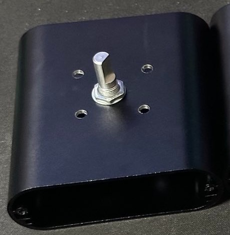
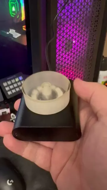
This project box, however, would require some modifications to allow it to work. My plan was to put the rotary dial right in the middle of the top of it. However, the LED ring would need some sort of insulator, otherwise it would likely cause a short between the wires and the enclosure. I worked up a quick spacer, including the holes for the required wires and volume knob. I placed the empty spacer on top of the case towards the middle, and used a punch to mark the knob and 4 wire lines for drilling. I drilled holes in the case using the closest sized drill bits I could find.
Problems for Future-Me
The case also was going to need a hole on one end for the USB-C from the Arduino. However, until it was more finalized, I wasn’t sure where the port would be. I put that off for later.
The First Signs of Trouble
When trying to insert the rotary encoder, I ran into my first problem. The rotary encoder was the perfect size for this enclosure, but only when it was in it’s final resting place. To get it into the case, it had to be put on it’s side, which made it impossible to get in and the shaft into the drilled hole. I ended up having to very carefully take apart the rotary encoder, insert it into the enclosure, and reassemble it. It was a lot like a ship in a bottle, but it was do-able.
Finishing the Spacer Assembly
With the rotary encoder in the enclosure, I soldered 3 wires to the 3 important pads on the LED ring, and ran them through the spacer. Then the rotary encoder’s nut went onto the threads, locking everything in place. I crimped some Dupont connectors I had laying around onto the end of the 3 wires in preparation for connecting them to the main board.
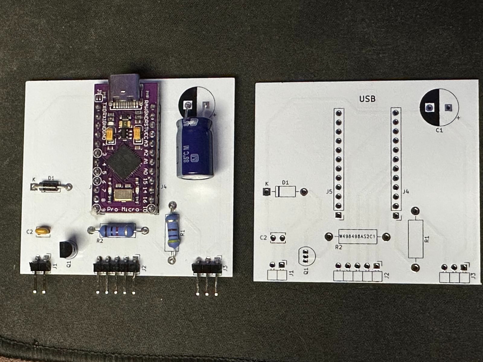
From Breadboard to Protoboard (Yuck)
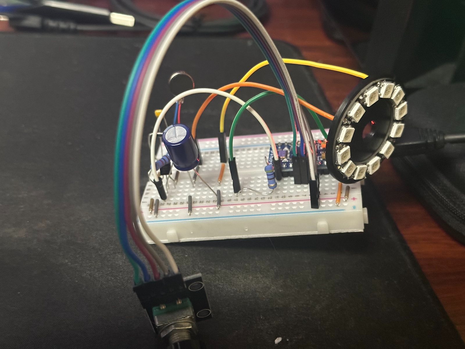
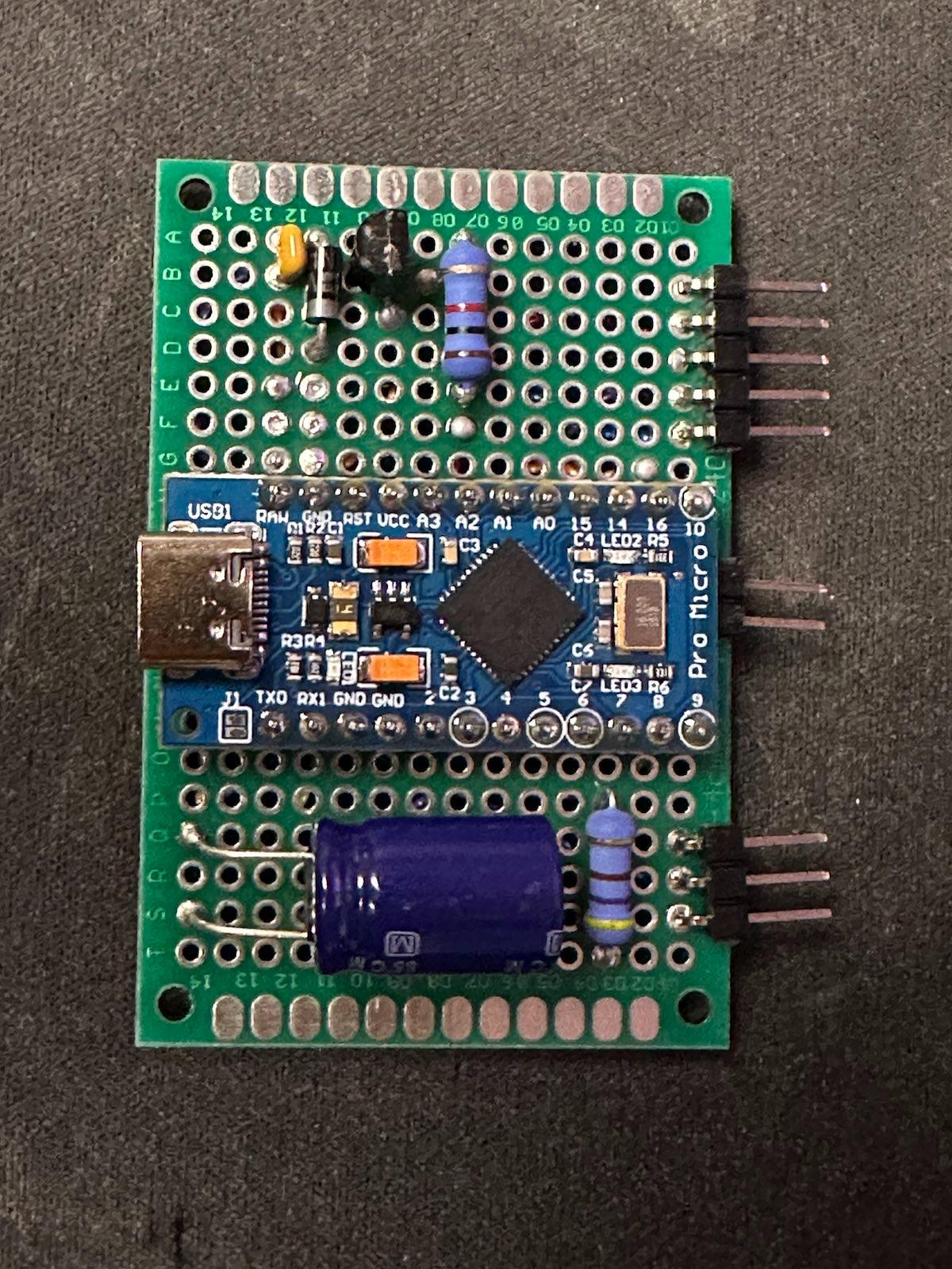
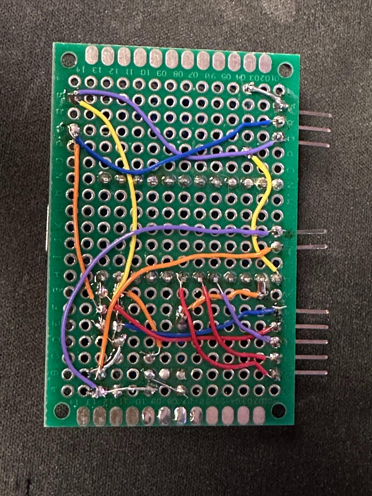
For testing, I initially used a breadboard. I flashed the firmware with Wolfgang’s original code. It worked spectacularly, strewn all across my desk, with parts hanging everywhere. I eventually got comfortable enough with it, that I went to a protoboard, which matched the size of the enclosure. I’m not a big fan of protoboard, and you can see why. Look at how busy the bottom of the board gets, and how easy it is to make a mistake. Also, considering that I was tasked with making 4 of these for my friends and me, it was not very reproducible.
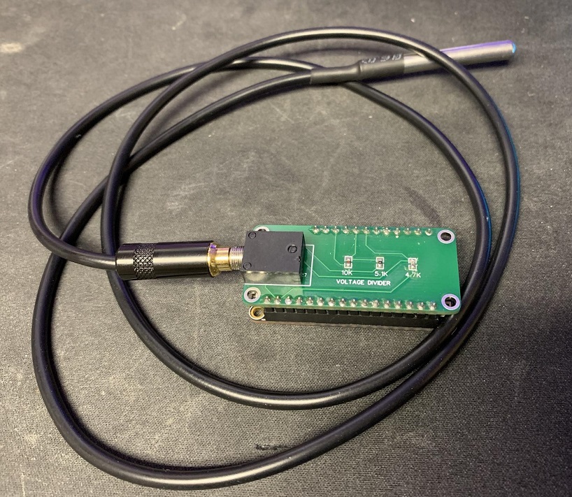
Making a Custom PCB
Using KiCad, my trusty PCB tool, I went to re-creating the schematic file. It isn’t anything overly complicated, and matches Wolfgang’s Fritzing schematic pretty closely.
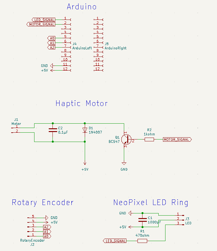
I then created a PCB, trying to keep the USB port of the Arduino at one end, and the angled pin headers at the other end, so they’d be managable. The large capacitor took up a decent amount of space, so it was left in the corner, and everything else just ended up where it would fit. I was able to get it all on a single layer, with the back being a solid ground plane.
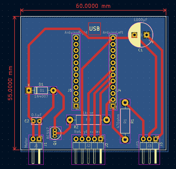
I’ve placed the KiCad files into GitHub. If you’re downloading the PCB files to make some of your own, I’d highly recommend checking out PCBWay. I used them for my boards, and they came out excellent. They were also very inexpensive. In addition to custom PCBs, they can also do 3D Printing and CNC/Machining. I have a couple projects that require aluminum, so I look forward to trying out the CNC projects in the future.
I picked the white PCBs:
If you’re designing a circuit in KiCad, PCBWay now has a one-click plugin to automatically submit your PCB design and create an order. I wish I would have known about this plugin earlier.
Modifying the Arduino Code
Since I had very little experience with PlatformIO, I wanted to convert the Arduino code from Wolfgang into a PlatformIO project. I ended up having to switch around a few of the rotary knob wires, and changed the brightness of the LEDs, but it’s otherwise mostly a direct copy. I placed the code out on Github
The Knob
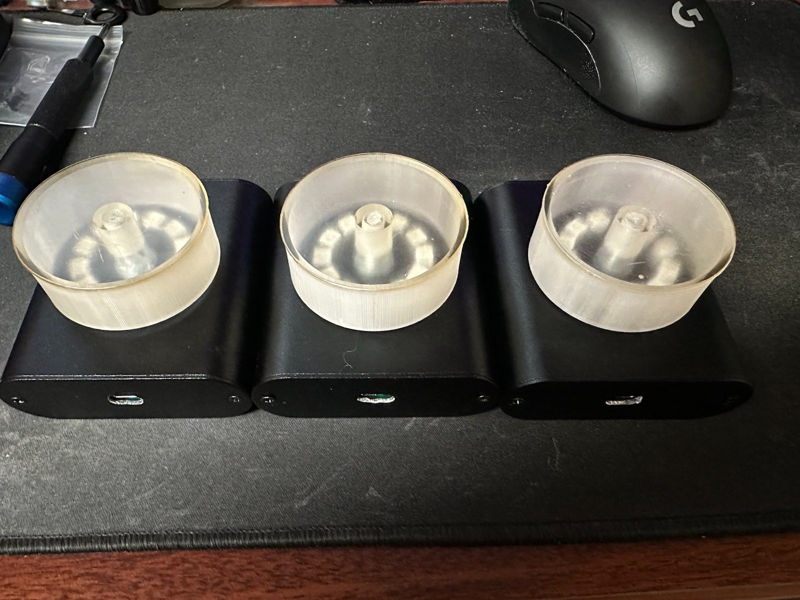
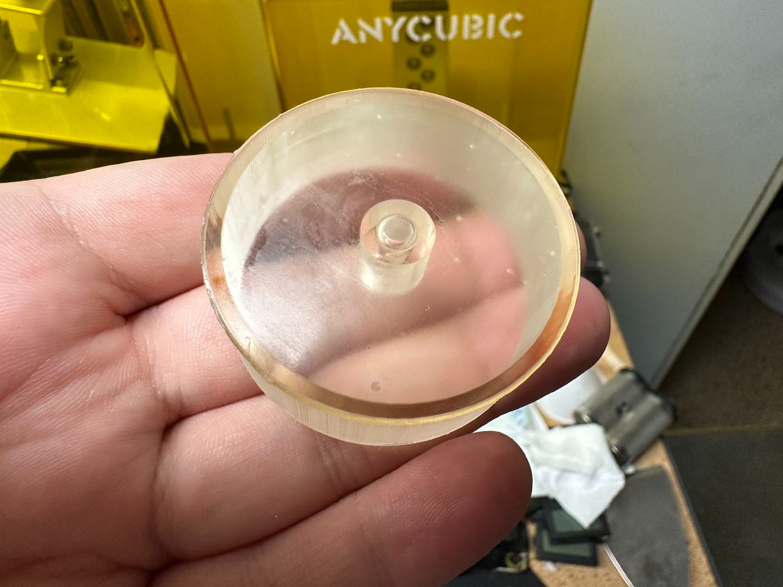
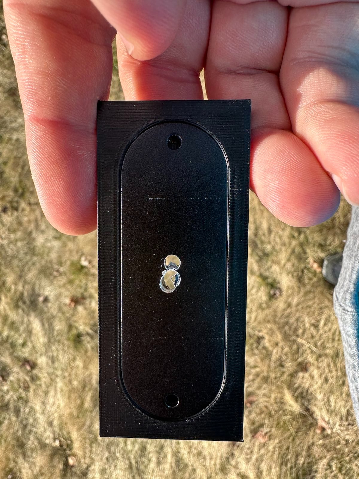
I liked the knob that Wolfgang used, but I really wanted it to be clear to let the LEDs brighten up the room. I used some clear resin, and tried several orientations to get it right. I kept having a lot of unsightly marks from the supports, however.
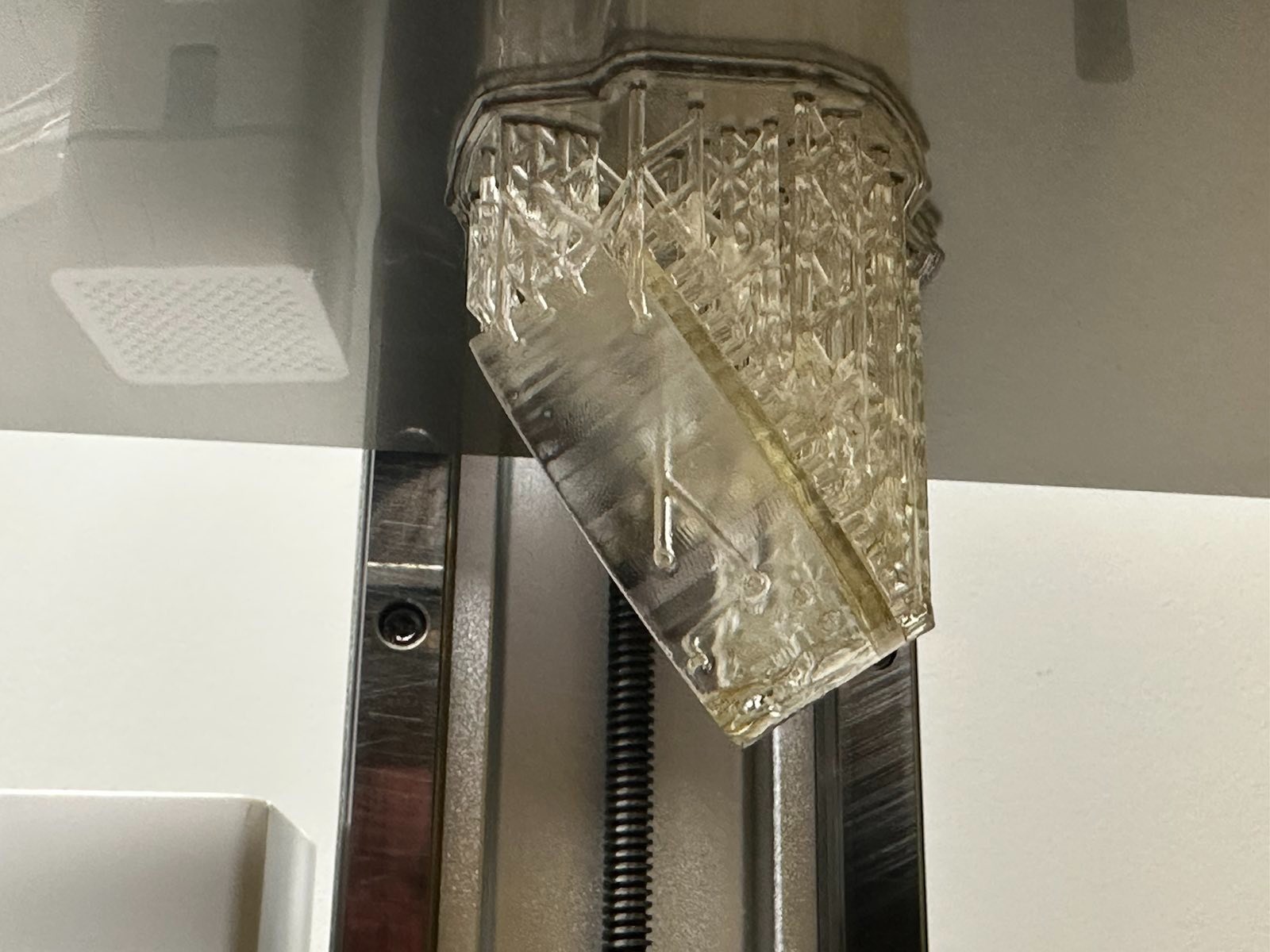
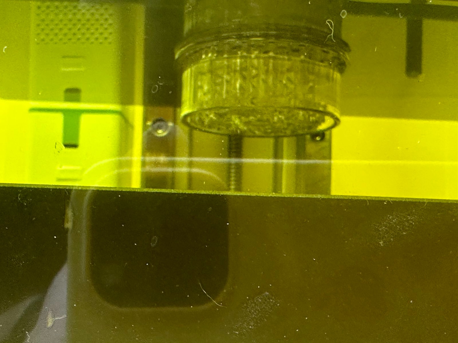
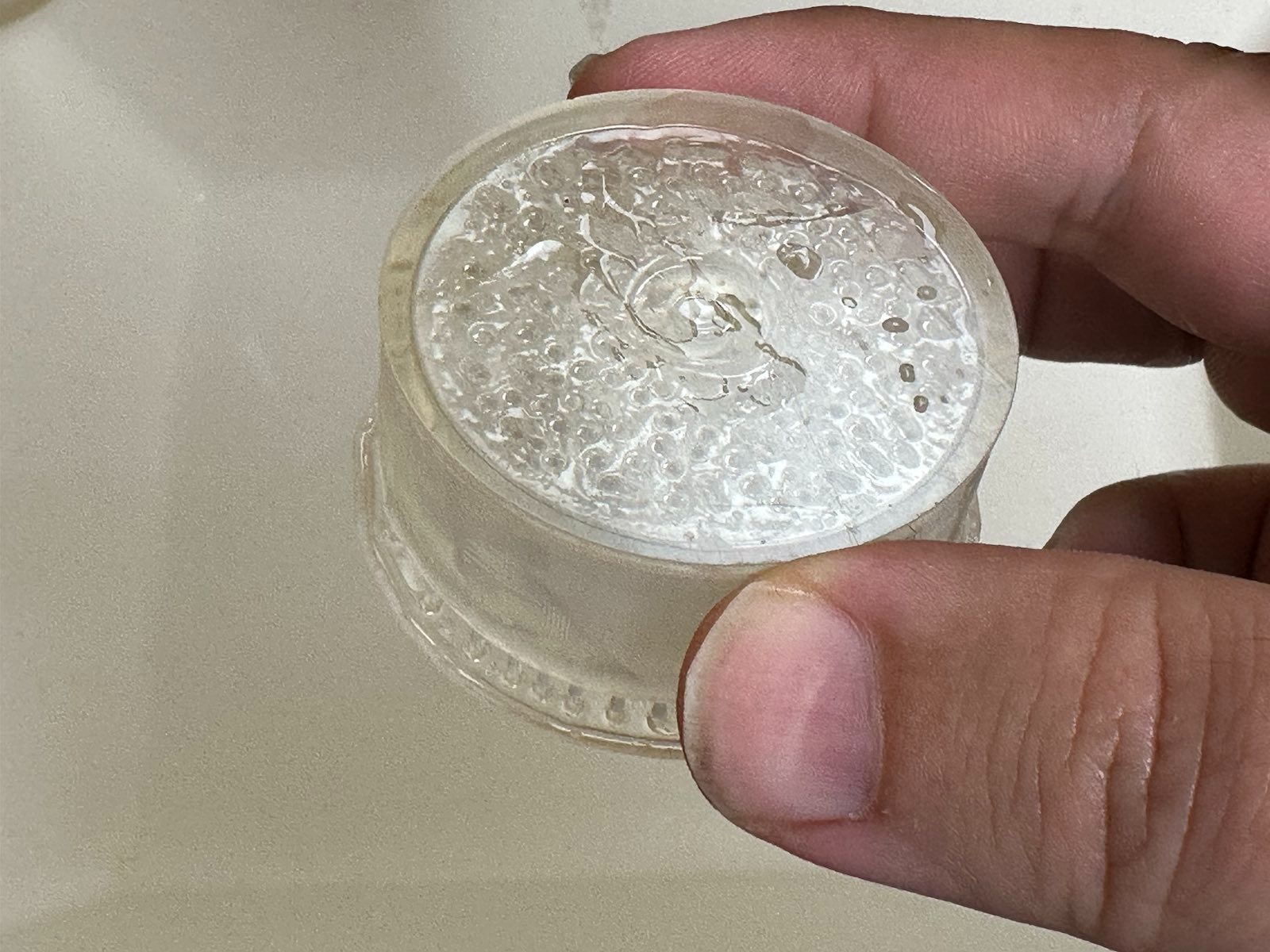
The best resolution I had, was to print it upside down, directly on the print bed, with no supports. This gave a clean layout, although it did have some elephant foot. However, it looked nice.
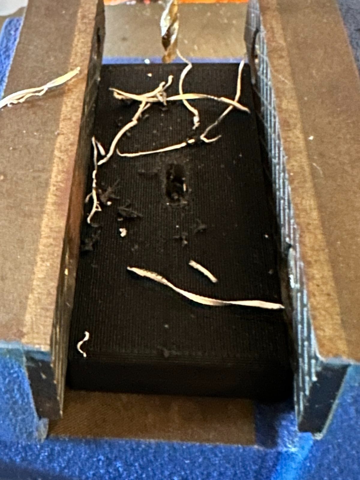
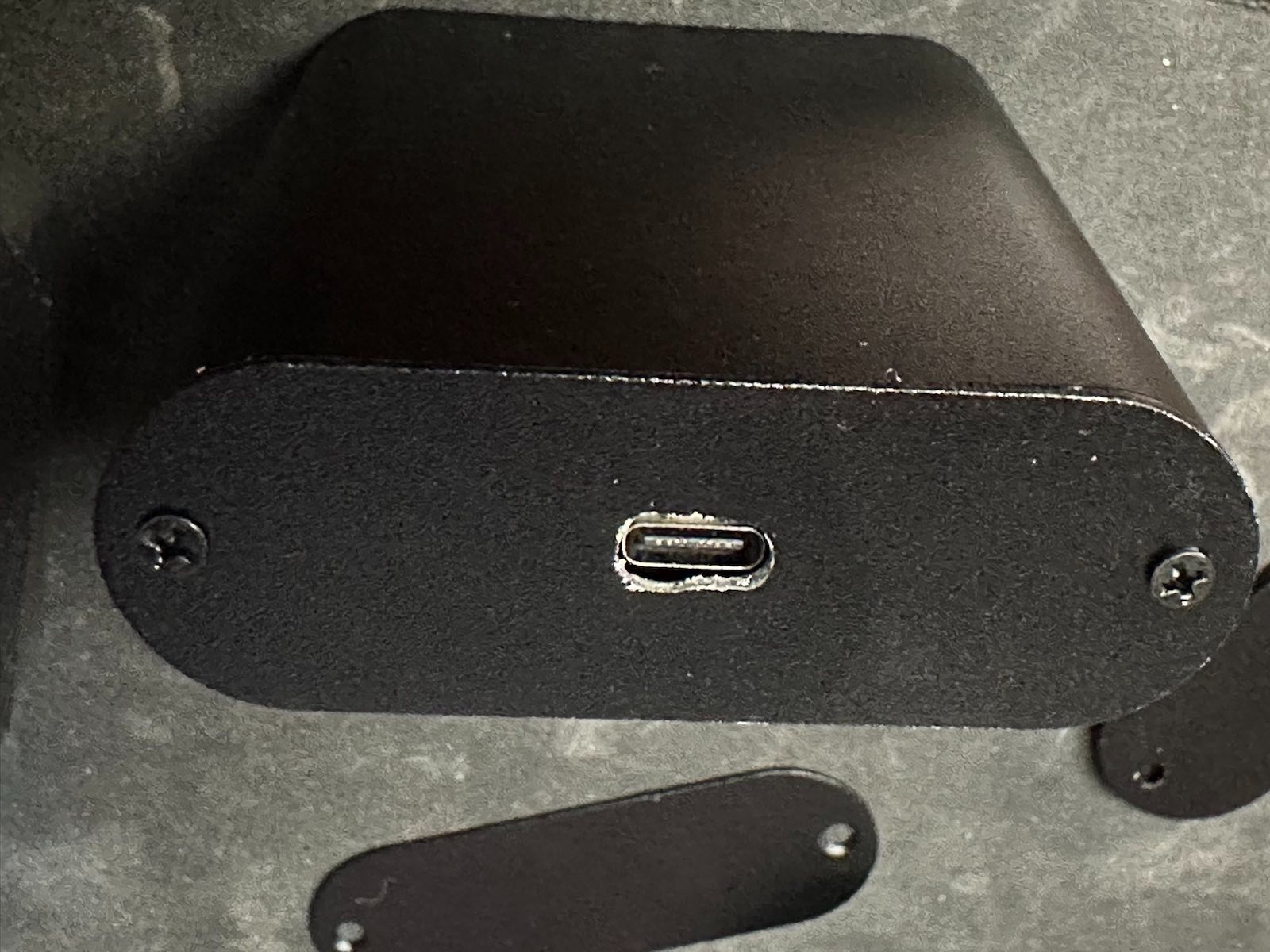
USB Holes and Jigs
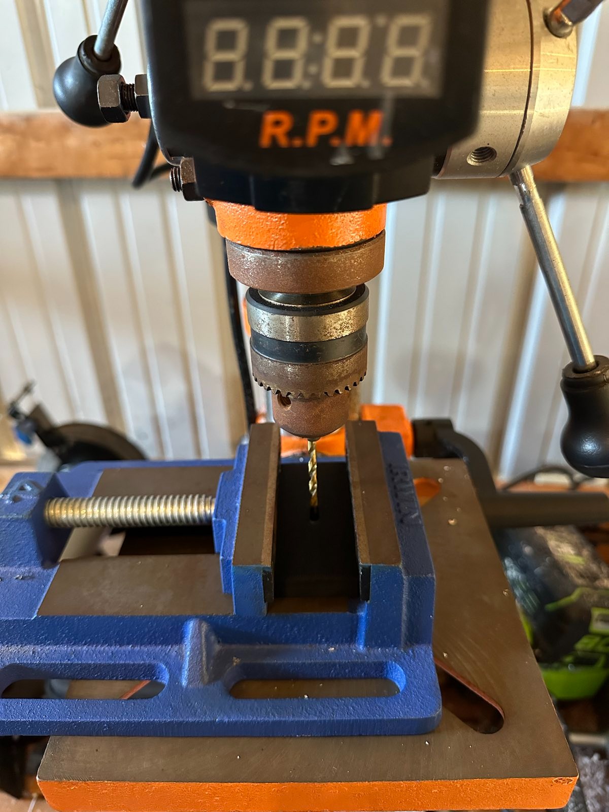
The only real remaining part of the build was making it so that the USB port of the Arduino was possible to be reached without leaving the side off. I created a jig which perfectly lined up the USB-C (probably accurate enough for USB-Micro, too) port on the enclosure end, so that it could be drilled in a drill press. I tried doing 3 of them at once, which was likely a mistake, causing things to not look amazing. I still think this is a good way of doing it, but may need to put more thought into the jig. Perhaps having a second part on bottom that pushes the metal upwards, preventing any sort of movement? Either way, with a little bit of filing with some hand files, it turned out “good enough”, although it’s probably my least favorite part of the project.
The End Result
Final BOM:
This should look familiar if you read Wolfgang’s post
Enclosure
Eightwood Aluminum Enclosure Electronics Box
Electronics
Arduino Pro
Note: I used the USB-C models, but USB Micro would work just fine, too.
Rotary Encoder Knob
Note: Be sure to get the ones that have threads on the barrel. The first set I bought did not, and was useless for this project.
1Kohm Resistor
Note: 1Kohm resistor is for the haptic motor
470ohm Resistor
Note: 470ohm resistor is for the LED strip
Dupont Connectors
Note: This is an optional part, but makes it a lot easier to debug and deal with.
")